Views: 7 Author: D and D Hardware Publish Time: 2021-01-23 Origin: D and D Hardware


These standards are recommended by the Hollow Metal Manufacturers Association as representing the long accepted usual preferences of both architects and users under normal conditions of use. Under some circumstances these standard locations are inadvisable for certain items based on accessibility codes. For example, a lower position for the deadlock is possible, when intended usage by small children or handicapped persons necessitates require positioning the user handled items in other than these recommended standard locations.

Hardware location and floor conditions
As shown on the drawing, all hardware items except the upper and intermediate hinges are located by fixed dimensions from the floor to the centerline of the item, making the locations of all user-handled items at the same level for all door heights. The floor is defined as top of the concrete or structural slab.

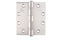
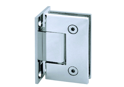
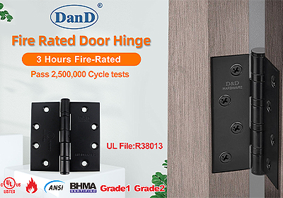
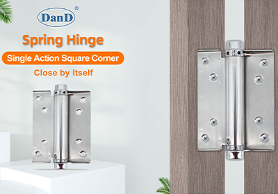
Butt Hinge
The three hinges shown on the drawing are recommended for doors over 5 ft. 0 in. (1524 mm) and including 7 ft. 6 in. (2286mm) in height. For doors of greater heights, where four or more hinges are used, the top and bottom hinges are located as shown, with the intermediate hinges being equally spaced between them. The hinge backset (the dimension from the stop face, or narrow side, to the edge of the hinge cutout) is 1/4 in. (6.4mm).

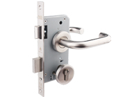
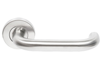
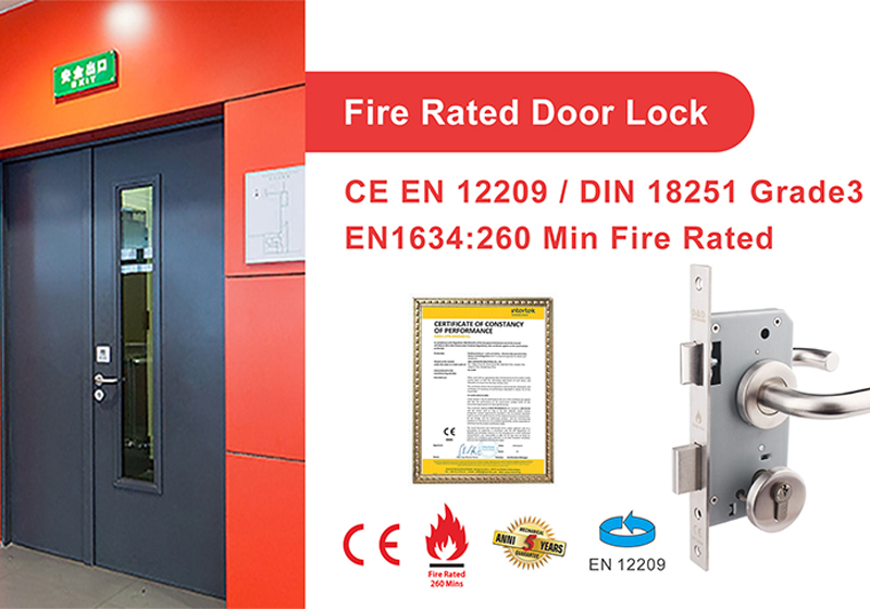
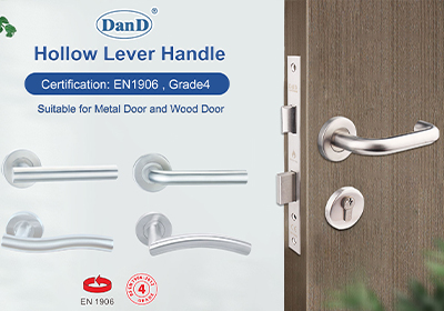
Lock Set
Regardless of the type of lock or latch used, the centerline of the lever or knob is located at the 38 in. (965mm) from the floor, for the convenience of the user. This will result in some variation in the strike location, depending on the type of lock used.

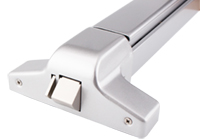
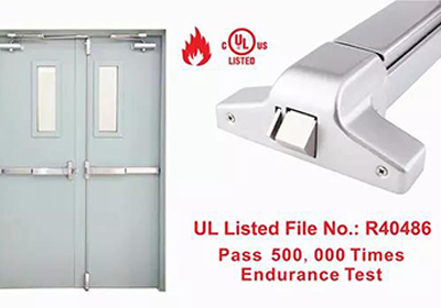
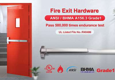
Panic Exit Hardware
Locations may vary depending on hardware manufacturers’ recommended locations or as required by code.

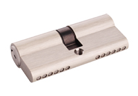
Auxiliary Deadlock and Latch
The recommended location for the deadlock is 46 in. (1168mm) to centerline positioning it so as to avoid interference with through bolts and preparations for other hardware. ADA requires that the centerline of operating element of cylinder be no more than 48 in. (1219 mm) above floor.
Push-Pull Hardware
The recommended location for the center of the grip on a door pull or on a push plate, and the centerline of a push/pull bar is 46 in. (1168mm).

Roller Latch
The recommended location is 46 in. (1168 mm) to centerline of latch. Roller latches are generally used with dummy knobs or with push/ pulls.

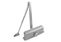
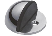
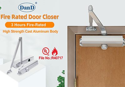
Door Control Devices (Closers, Holders, Stops, Operators)
Locations may vary depending on hardware manufacturers’ recommended locations or as required by code.

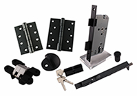
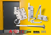
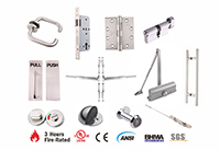
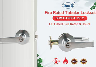
A strong door lock, high durability hinge, long-lasting door handles, and a tough face plate are absolute necessities. Consumers will want hardware that’s easy to operate, but hardware that provides excellent security and durability at the same time.
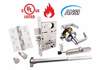
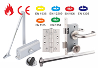
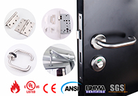
D&D's metal door hardware are used for rigorous safety testing (including BS EN, CE, UL, ANSI and BHMA) for education, healthcare, hospitality, residential and commercial applications.
For further information about door hardware or any of our services, click here.
Reference
HARDWARE SELECTION FOR HOLLOW METAL DOORS AND FRAMES-HMMA 831-11
David Jian
Mob: 0086-139 2903 7292
Email: David@dndhardware.com, sales@danddhardware.com
Jobby Zhang
Mob: 0086-137 2599 9617
Email: jobby@dndhardware.com